Creating a Virtual Alarm
NOTE: In addition to alarms found in GSMs within the same subnet as your local Application Server, you can also create virtual alarms with sub-alarms from remote GSMs residing on Application Servers outside the local subnet. In order to do this, you must first type the IP addresses of the remote GSMs within the Service and alarm discovery area of the iControl Lookup locations page of iControl. |
REQUIREMENT: |
Before beginning this procedure, make sure you have opened the GSM Alarm Browser for the appropriate GSM ( click HERE). |
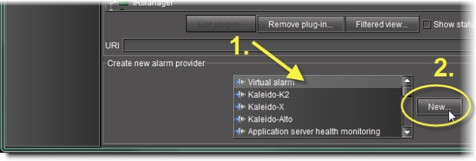
1. In the Create a new alarm provider area of the GSM Alarm Browser, click Virtual alarm.
2. Click New.
[ Graphic ]
System Response: The Build virtual alarm window appears.
3. In the Status logic section, select one of the following three options:
• Virtual alarm status is best status among selected alarms (AND) — Choose this option to have the contribution of the sub-alarms calculated using the optimistic version of the alarm logic tables.
• Virtual alarm status is worst status among selected alarms (OR) — Choose this option to have the contribution of the sub-alarms calculated using the pessimistic version of the alarm logic tables. This is the most common option, since it brings changes in the status of any sub-alarms to the attention of the operators.
• Virtual alarm status is critical if selected alarms differ (XOR) — Choose this option to have the contribution of the sub-alarms calculated using the XOR version of the alarm logic tables. This causes the virtual alarm to reflect whether or not all of its sub-alarms have the same status. If all sub-alarms are the same (and in error), the virtual alarm will be green. If, among the errored sub-alarms, there are one or more discrepancies in status, the virtual alarm’s status will be red.
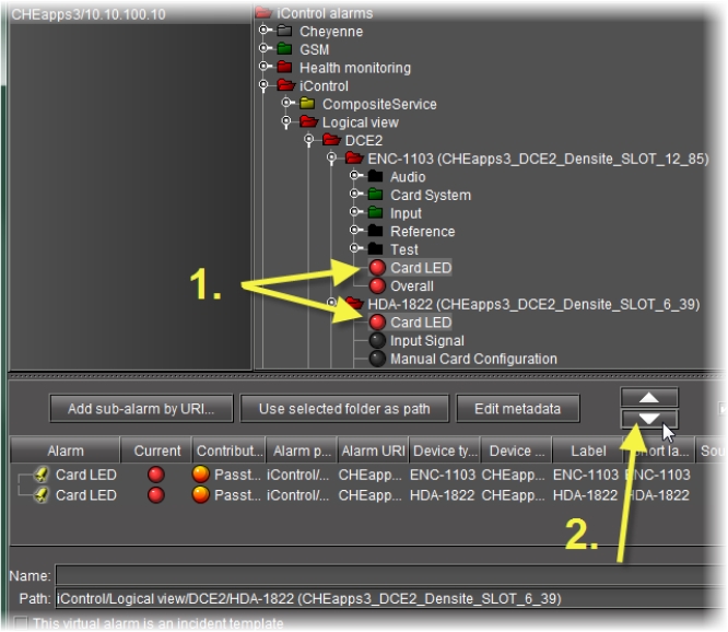
4. Select the alarms that are to be sub-alarms of the new virtual alarm, and then click the large down arrow button to transfer them to the table in the bottom half of the window.
The alarm hierarchy displayed in the Build virtual alarm window is the same as the one in the GSM Alarm Browser.
[ Graphic ]
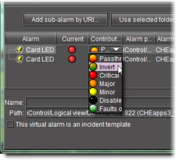
5. The table displays various details about the sub-alarms you have selected, including their Contribution, which defines how a sub-alarm will pass its status on to the virtual alarm. The default contribution value is Passthrough, which means the sub-alarm will pass its status unaltered to the overall calculation of the virtual alarm.
It is possible to override the error status of sub-alarms when they are triggered. This is useful when, for example, a device is only able to report a status of either normal (green) or error (red), but you want the error condition to be reflected as a warning (yellow) in the virtual alarm. To change a sub-alarm’s contribution, click in the Contribution column, and then select the status you want the virtual alarm to use when an error occurs.
[ Graphic ]
For example, if a sub-alarm goes from green to orange or red, but the selected contribution is yellow, the virtual alarm will “see” yellow (the virtual alarm’s overall status may still depend on other sub-alarms).
The Invert contribution allows performing a logical “NOT” calculation on sub-alarms. This feature can be used, for example, to report alarms from GPI inputs. It can also be used to handle cases where an error is expected, and not seeing an error is a sign that something probably went wrong. The table below describes the result of inverting sub-alarms:
[ Table ]
Sub-alarm Status | Inverted Contribution |
NORMAL | ERROR |
MINOR | NORMAL |
MAJOR | NORMAL |
CRITICAL | NORMAL |
NON-EXISTENT | NON-EXISTENT |
PENDING | PENDING |
DISABLED | DISABLED |
UNKNOWN | UNKNOWN |
Selecting the Faults only contribution causes a sub-alarm to be mapped to NORMAL unless it’s in one of the fault statuses—usually CRITICAL, MAJOR, and MINOR. The list of fault statuses can be modified by using the setFaultSeverities( ) property. See the GSM Scripting Manual for details.
NOTE: If the sub-alarm’s fault condition is cleared, its contribution will always be green, unless the value specified in the Contribution column is black. |
6. Specify a name for the new virtual alarm in the Name field.
7. Specify a path for the new virtual alarm.
By default, virtual alarms are created under the Virtual alarms folder in the Alarm Browser hierarchy, but you can organize your virtual alarms however you see fit. Type the path to the destination folder for the virtual alarm in the Path field. Use a forward slash character (/) to separate folder names. If the folder doesn’t exist, it will be created automatically.
Alternatively, as a shortcut for existing folders, you can select an existing folder in the alarm browser hierarchy, and then click the Use selected folder as path button. The location of the selected folder will appear in the Path field.
[ Graphic ]
Using the selected folder as a destination folder
8. Click OK.
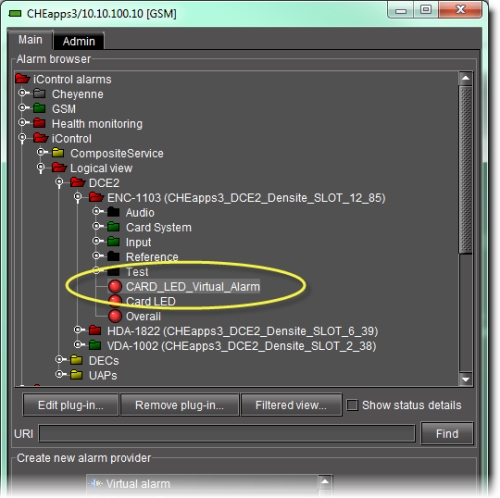
System Response: The Build virtual alarm window closes and the newly created alarm appears in the specified folder in the Alarm Browser window.
[ Graphic ]
Newly created virtual alarm (circled)