| Channel |
The name of the GV I/O channel. |
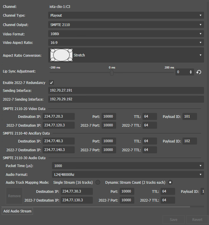
| Channel Type |
The Channel Type selected is Playout for the GV I/O Live Ingest and Playout Server.
Note: The GV STRATUS
desktop application needs to be restarted after changing
a GV I/O channel type from Playout to Record or from
Record to Playout in order to see updated configuration
options in the Channel Panel tool.
|
| Channel Output |
Output signal type for the selected channel of the GV I/O Live Ingest and Playout Server.
Select the channel output as below:
- Unassigned - The channel output
is set to this initial setting by default. No other
settings are configurable when this option is selected.
Note: Changing a channel's I/O configuration to
Unassigned will set channel configuration
information to a default state and release any
SabreTooth licenses associated with the
channel.
- SMPTE 2110 - Configures the channel to use 10/25GigE SFP
output. Requires the GVIO-SVR-IP license per channel and
GVIO-HW-CX5 hardware configuration.
|
| Video Format |
Select a format of 480i (NTSC), 576i (PAL),
720p, or 1080i. |
| Video Aspect Ratio |
Select an available aspect ratio of either 4:3 or 16:9. Only the 16:9 aspect ratio
is available if HD video format is selected.
|
| Aspect Ratio Conversion |
Select an aspect ratio conversion for the playout channel from the list below:
- Bar
- Half Bar
- Crop
- Stretch
|
| Lip Sync Adjustment |
Move the slider bar between -200ms to +200ms to adjust the lip sync of clip audio
relative to the video rendering during playout. You can also
enter a value manually or click the Revert to
Default button to load the default
value. |
| Enable 2022-7 Redundancy |
Select this box to enable redundancy as a playout backup. This setting is only
available when SMPTE 2110 is selected for
the channel output. When the 2022-7 redundancy check-box is
selected, a 2022-7 Sending Interface (IP address) is also
required, and it represents the IP address of a second GV
I/O output. The 2022-7 Destination IP, 2022-7 Port, and
2022-7 TTL of video, audio, and ancillary data must also be
entered to support playout redundancy.
|
| Sending Interface |
For a channel configured for SMPTE 2110 output signal type, enter the IP address that
goes with the SFP connector used to transmit the media stream. |
| SMPTE 2110-20 Video Data |
SMPTE 2110 Video stream settings |
| Destination IP |
Enter the multicast IP address of the multicast group to send the video_type media
stream to. |
| Port |
Enter the port number on the specified multicast IP address for the video
stream. |
| TTL |
Enter the Time-To-Live (TTL) value that tells a network router whether or not the
video data has been in the network too long and should be
discarded. |
| Payload ID |
Enter the payload identification number for the video stream. |
| SMPTE 2110-40 Ancillary Data |
SMPTE 2110 Ancillary data settings |
| Destination IP |
Enter the multicast IP address of the multicast group to send the ancillary_data_type
media stream to. |
| Port |
Enter the port number on the specified multicast IP address
for the ancillary data stream. |
| TTL |
Enter the Time-To-Live (TTL) value that tells a network router whether or not the
ancillary data has been in the network too long and should be
discarded. |
| Payload ID |
Enter the payload identification number for the ancillary
data stream. |
| SMPTE 2110-30 Audio
Data |
SMPTE 2110 Audio stream settings |
| Packet Time |
Select the delay time between 125 to 4000 (micro-seconds) for the audio data. |
| Audio Format |
Set the audio format to L24/48000 Hz.
Note: Loading a clip to the channel for playout will fail if
audio format is set to "L16/48000 Hz".
|
| Audio Track Mapping Mode |
Select the audio track mapping mode either a single audio stream with 16 tracks, or a
dynamic stream of up to 8 audio streams, with 2 tracks
each. |
| Destination IP |
Enter the multicast IP address of the multicast group to send the audio_type media
stream to. |
| Port |
Enter the port number on the specified multicast IP address
for the audio stream. |
| TTL |
Enter the Time-To-Live (TTL) value that tells a network router whether or not the
audio data has been in the network too long and should be
discarded. |
| Payload ID |
Enter the payload identification number for the audio data
stream. |
| Add Audio Stream |
Click the Add Audio Stream button if you want to add more streams of audio data. Then
enter the destination IP, port number, and TTL value of the
audio stream. |