Adding Physical Router Levels
The physical levels from which the router is going to be built must be defined. Typical levels include video, audio 1, audio 2, etc. These levels each represent a physical device. Each level must be named, and its type and size specified.
IMPORTANT: Using Telecom and Data Routers |
• Network series RS-422 Data routers have to be configured as an audio level. Select an appropriate audio frame type. For example, if you have an 8 × 8 RS-422 router, you should select Network Audio 8 × 8 frame type. |
• Network series Telecom routers are configured to work as a video level so you can use an appropriate video frame. For example, if you have an 8 × 8 Telecom frame then you should select Network Video 8 × 8 frame type. |
NOTE: Although it is possible to perform the following procedure as a stand-alone task (assuming all stated requirements are met), Grass Valley recommends you familiarize yourself with the sample workflow on page 58 in which this procedure is only one step within a sequence. |
REQUIREMENT: |
Before beginning this procedure, make sure you have opened Router Manager Configurator ( click HERE). |
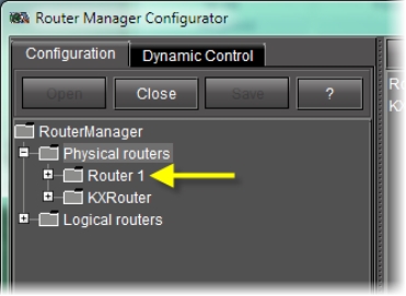
1. In Router Manager Configurator, in the left pane, select the physical router you wish to configure.
[ Graphic ]
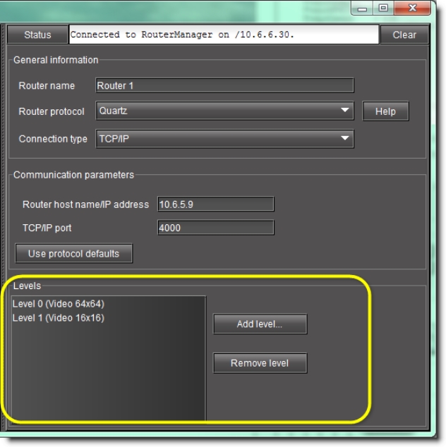
System Response: The list of existing levels appears under Levels.
[ Graphic ]
2. Click Add level.
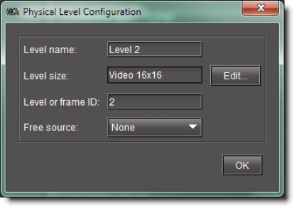
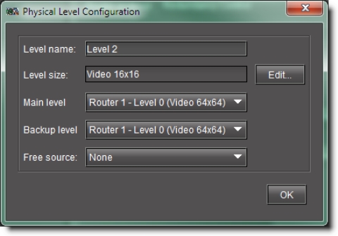
System Response: The Physical Level Configuration window appears. Its content varies according to the selected router protocol:
[ Graphic ]
Figure 4-4: Physical Level Configuration window (for most protocols)
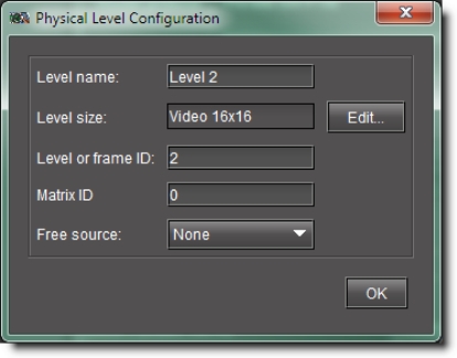
Figure 4-5: Physical Level Configuration window (for a Snell SW-P-08 device)
Figure 4-6: Physical Level Configuration window (for a Redundancy Control device)
3. In the Level name box, type a name for this level.
4. Click Edit.
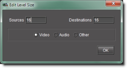
System Response: The Edit Level Size window appears.
[ Graphic ]
5. Specify the number of sources and destinations associated with the physical level.
NOTE: The three option buttons labeled Video, Audio and Other are used for Network Electronics routers only, for which levels must be classified as either Video or Audio. These settings are ignored by routers from other manufacturers. |
6. In the case of a Snell SW-P-08 device, type the appropriate value in the Matrix ID box (click Help for more information).
7. In the case of a Redundancy Control device, select the appropriate main level and backup level from the lists (click Help for more information).
8. Click OK to close the Edit Level Size window.
9. Click OK to close the Physical Level Configuration window.
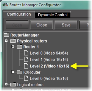
System Response: At this point, you have added a level to a physical router, which appears in the Levels list under the Configurations tab.
[ Graphic ]
Figure 4-7: Newly added physical router level
NOTES: |
• If you have several 16 × 2 frames configured to work together then you have to add only one frame and select an appropriate frame type on the Edit Physical Level window. For example, if you have three 16 × 2 video frames configured to make a 48 × 2 router then you should select a Network Video 48 × 2 frame type. |
• When the tab is opened, data boxes will appear in which the name, Frame Type, Frame ID and Physical Level ID can be entered, and two charts (tab-accessed) will appear below in which the Sources and Destinations can be identified and labeled.. These should conform to the actual physical connections made to the router being controlled. |
The Frame ID in the physical level configuration is the frame address that is set by the DIP switches on the router frame. The Physical Level ID is the internal identifier of the frame and should be unique within each physical router. If it's not unique, then you will get an error message when you try to save the changes. The Matrix ID is an optional entry for a Probel router.
The Physical Router definition is now complete.