EDIUS 7 Online Help
Reference ManualHardware Setup Guide
Installation Manual
User Guide
The video finely displayed on a PC monitor may cause the problems like highlight/shadow detail loss when actually displayed on a TV monitor.
This problem occurs when the luminance range is smaller than that allowed to be displayed on a PC monitor. To display the video on a TV monitor, you need to adjust video signal in advance.
To adjust the video signal range that is hard to judge visually, measure it with Vector Scope/Waveform. Vector Scope adjusts the color balance, and Waveform adjust the brightness to be the average value of the whole display.
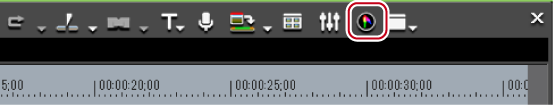
The [Vector Scope/Waveform] dialog box appears.
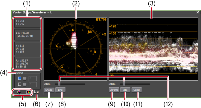
[Vector Scope/Waveform] Dialog Box
 Alternative
Click [View] on the menu bar, and click [Vector Scope/Waveform].
 Note
NoteDisplaying Vector Scope/Waveform increases the CPU loading.Display it only when required.
|
(1)
|
Information area
|
Display coordinate values (X, Y) on the screen and YUV, IRE and RGB values. |
|
(2)
|
vector scope
|
Display color distribution in the image shown in Recorder. The circle represents the color circle, and the distance from the center represents the saturation Click on the vector scope to be expanded, and right-click it while keeping expanded to be contrasted. |
|
(3)
|
Waveform
|
Display chroma and luminance levels of the image on Recorder. Click on the waveform to be expanded, and right-click it while keeping expanded to be contrasted. |
|
(4)
|
[Select]
|
Display the information of a Y-axis (vertical) position. Check this item, click The box shows the Y coordinate values of that position, and the displays of the vector scope and waveform are fixed to the color data of that position. Even after you uncheck the item, the last display of the vector scope and waveform is reproduced when you check the item box again. |
|
(5)
|
Show/Hide
|
Switch the show/hide for the vector scope/waveform. |
|
(6)
|
L/R switch
|
In the stereoscopic edit mode, this is displayed when the video of both the L and R sides are displayed in the preview window. The vector scope or waveform on the L or R side only is displayed. |
|
(7)
|
[Shade]
|
Display the color distribution by dots on Vector Scope. |
|
(8)
|
[Line]
|
Display the color distribution by lines connecting between dots on Vector Scope. |
|
(9)
|
[Chroma]
|
Display only the color tone factor in the 0 IRE center of the waveform. |
|
(10)
|
[IRE]
|
Display only the luminance factor in the waveform. |
|
(11)
|
[Comp]
|
Display the composite signal of color tone factor (Chroma) and luminance factor (IRE) in the waveform. |
|
(12)
|
Luminance sliders
|
Use these sliders to adjust the luminance of the monitor. |
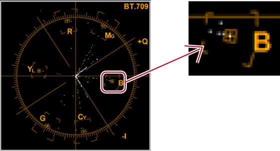
Measure the color balance using a vector scope
Measure the color bar recorded in the source clip using the [Vector Scope/Waveform] dialog box.
An adjustment is needed when the light representing the color distribution is shifted far from the reticule center of the vector scope.
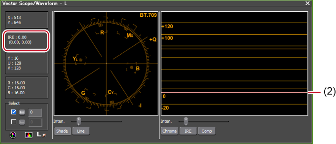
Measure the luminance with waveform to check if it is within the appropriate range
When you place a white color matte clip created in the safe color range on the timeline and measure it in the [Vector Scope/Waveform] dialog box, IRE100 appears (at the position of (1)).

In the case of black color matte clips created in the safe color range, IRE0 appears. (at the position of (2)) Adjustment is not necessary when IRE is a minus value.
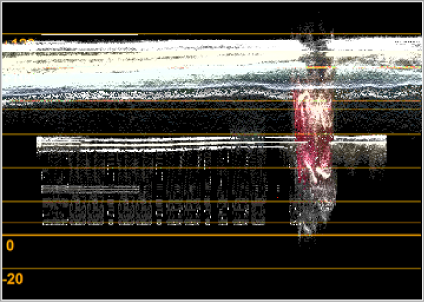
If the luminance is high, the following screen is displayed.
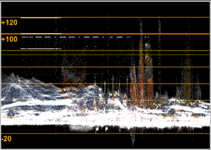
If the luminance is low, the following screen is displayed.
In this case, you need to adjust IRE within the range between 0 and 100. To easily adjust it, apply the color balance of a video filter to the clip. Open the settings dialog box of the color balance, and select the [Safe Color] option to automatically adjust the IRE of the clip between 0 and 100.

Although Safe Color clips a range of luminance 16-235 and chroma 16-240, and the chroma is not automatically included in the safe area, it is calculated to include luminance/chroma within IRE0-100.

 , and then click a position on Recorder screen. You can also directly enter the scanning line.