The connection information for the external device used for capturing or exporting (camera, deck, web camera, microphone, input/output hardware) are registered and managed as the preset with the device preset. Capturing or exporting operation can be performed smoothly by loading the registered device preset.
Before registering device presets, connect the external device (e.g. camera) used for input/output to your PC, and turn it on.
Connecting to External Devices

External devices in which file-based video or audio is recorded (e.g. CD/DVD, AVCHD camera, removable media such as SD memory card, XDCAM EX device) are not required to be registered as device presets.
1) Click [Settings] on the menu bar, and click [System Settings].
|
|
|---|
|
2) Click the [Hardware] tree, and click [Device Preset].
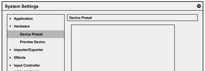
The [Device Preset] screen appears.
3) Click [New].
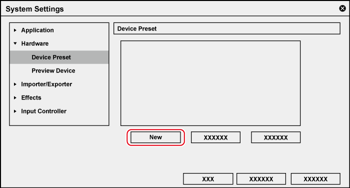
[Preset Wizard] will start up.
 Alternative
Right-click a blank area in the device preset list, and click [New].
4) Enter the name of the device preset.
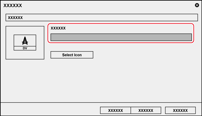
5) Click [Select Icon], select the icon image, and click [OK].
To use any image you like, click [...] and select a file.
6) Click [Next].
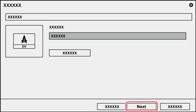
The [Input H/W, Format Settings] screen appears.
7) Set each item and click [Next].
The [Output H/W, Format Settings] screen appears.
The output target device (such as a tape deck) that can be controlled from EDIUS is setup with [Output H/W, Format Settings] in the device preset. The video is always output according to the project setting when the output is performed from the output terminal unavailable for the deck control. Configure the setting in [Preview Device] for the output from the output terminal unavailable for the deck control.
8) Set each item and click [Next].
9) Confirm the details, and click [Done].
The icon of the newly created preset is displayed in the device preset list.
|
Device preset list |
Displays a list of device presets. The list can be resorted by dragging the icons. The list is not displayed when there are no device presets registered. |
|
[New] |
Create new device presets. |
|
[Modify] |
Change the settings of the selected device preset. |
|
[Delete] |
Delete the selected device preset. |
The following explains settings for two instances, when using the IEEE1394 terminal provided as standard on the PC for input and when inputting from a DirectShow capture device.
For more information on settings when using Grass Valley products for input, see the user manual included with the product.
|
[Interface] |
Click this item to select the interface to use for input. When connecting an HDV device to the IEEE1394 terminal provided as standard on a PC for input, select [Generic HDV]. When connecting a DV device to the IEEE1394 terminal provided as standard on a PC for input, select [Generic OHCI]. To input from a DirectShow base video capture device or audio capture device, select [DirectShow Capture]. When the interface to use for input is selected from the list, the content of each of the items such as [Stream] switches to match the selected interface. To disable use of an interface for input, select [Not Select]. |
|
|
[Stream] |
When [Generic HDV] or [Generic OHCI] is selected at [Interface], the stream is fixed to [Input]. You can make input settings by clicking [Settings]. [Settings - Input Settings] Dialog Box (Generic OHCI/Generic HDV) When [DirectShow Capture] is selected at [Interface], select your device. The displayed device name varies depending on your product. You can make device settings by clicking [Settings]. When your device is a video capture device, you must set the associated audio capture device. |
|
|
[Video Format] |
Select the video format for the source to capture. |
|
|
[Codec] |
Select the codec to use for capture depending on the video format. You can make codec settings by clicking [Settings]. [Settings - Grass Valley HQ]/[Settings - Grass Valley HQX] Dialog Box [Settings - MPEG2 Custom] Dialog Box [Settings - XDCAM HD422 Compatible] Dialog Box [Settings - XDCAM EX Compatible] / [Settings - XDCAM HD Compatible] Dialog Box |
|
|
[File Format] |
Select the file format of the captured clip depending on the video format. |
|
|
[Proxy File] |
Select a file (only high-resolution/high-resolution and proxy) to be created when capturing. |
|
|
[Audio Format] |
Select the audio format of the source to capture depending on the video format. |
|
|
[Audio Input] |
Select the audio input interface depending on the video format. |
|
|
[Convert 16Bit/2ch] |
Select whether to import audio by 16 -bit/2ch depending on the video formats. |
|
|
[Stereoscopic] |
Select [Separate L/R Clips] to capture the L side and the R side of the input video separately using the batch capture function. The recorded L and R side files are registered to the bin as stereoscopic clips. (The [Separate L/R Clips] setting is enabled while batch capturing.) |
|
* Selectable items differ according to the setting.
|
Input preview |
Displays the video from the input device when EDIUS recognizes the input device. |
|
[Setup Level] |
Set the setup level (black level). 0 IRE is used in Japan, and 7.5 IRE is used in North America. |
|
[Use cueup command if the DV deck supports it] |
Check this item to help speed up the cueup operation if the deck has the CueUp function. |
|
[Capture Preroll time] |
Set the preliminary operation time (preroll) from the capture position. |
|
[Default] |
Return the settings of items marked with * to their defaults. |
|
[Video Device] |
Displays the video capture devices connected to the system. Click [Video Setting] to display detailed settings depending on your video capture device. For more information on settings, see the manual for your device. |
|
[Audio Device] |
Displays the audio capture device connected to the system. Select the audio capture device corresponding to the video capture device from the list. To cancel this setting, select [Not assigned]. |
|
[Set video frame rate from audio sampling rate.] |
Check this item to calculate the frame rate from the number of samples and duration time of the audio. Uncheck this item to calculate the frame rate from the frame rate provided by the video capture device, and convert the audio sampling rate to match the frame rate. |
|
Codec settings |
[Online(SuperFine)] This item can be selected for a Grass Valley HQX codec. This setting provides the highest image quality, though the file size increases. Select this when importing at high image quality is needed. This item cannot be selected for a Grass Valley HQ codec. [Online(Fine)] This setting provides high image quality, though the file size increases. Select this when importing at high image quality is needed. [Online(Standard)] Normally, you can get sufficient image quality at this setting. [Offline] Select this item to encode at a lower bitrate. [Custom] [Q] and [Max size] can be adjusted. [Q] adjusts image quality. Set within the range 4 to 19 (0 to 18 in the case of a Grass Valley HQX).Setting a smaller value results in higher image quality. [Max size] sets the maximum bitrate. You can set to limit the file size that increases inadvertently as a result of excessive noise in the video. Setting value “100” % means the same bitrate before codec compression. For example, 100% for 1440x1080 59.94i is a bitrate of approximately 750 Mbps. To set the upper limit to 200 Mbps, set “27” % as the maximum size. |
|
|
|---|
|
|
[Bit Rate] |
Select a bitrate type. [CBR] sets a fixed transfer rate, allocating a fixed number of bits during the encoding process. Select a bitrate from the [Average] list. You can also enter a value directly. [VBR] sets a variable transfer rate, altering the number of assigned bits according to the complexity of the movement or image quality. Compared with [CBR], the media volume can be used more efficiently, and this enables more consistent image quality overall. Select a bitrate from the [Average] and [Max] lists. You can also enter a value directly. |
|
[Quality/Speed] |
Select quality from the list. |
|
[GOP Structure] |
For MPEG, a certain number of frames is considered as a group, and operations such as compression/enlargement and cut editing are performed on a GOP basis. A GOP comprises “I frame”, “P frame” and “B frame”. The I frame allows images to be reproduced independently, the P frame is for recording and reproducing only the differences with the preceding image, and the B frame reproduces images from the differences in the preceding and following images. Select I, P and B frame patterns of the GOP from the list. Normally, select [IBBP]. [I-Frame Only] is comprised of only I-pictures. Editing is made easier, but the amount of data increases in size. |
|
[Picture count] |
Set the number of frames included in a group. |
|
[Closed GOP] |
Check this item to complete information within each GOP. Although the amount of data increases, the video can be re-edited using software that supports GOP-based editing. Normally, leave this item unchecked. |
|
[Chroma Format] |
Select a YUV pixel format from the list. |
|
[Profile/Level] |
Select a profile & level. If [Chroma Format] is [4:2:0] and [4:2:2], the profile will be set to Main Profile and 422Profile, respectively. The level for SD image quality will be Main Level, and the level for HD image quality will be High Level. The profile & level changes according to the format selected in [Chroma Format]. |
|
[VBV Buffer Size] |
Select the setting method for the VBV buffer upper limit value. When [Default] is selected, the VBV buffer upper limit value is set using current settings. |
|
[Quality/Speed] |
Select quality from the list. |
|
[Closed GOP] |
Check this item to complete information within each GOP. Although the amount of data increases, the video can be re-edited using software that supports GOP-based editing. Normally, leave this item unchecked. |
|
[Bit Rate] |
Select a bitrate from the list. |
|
[Quality/Speed] |
Select quality from the list. |
|
[Closed GOP] |
Check this item to complete information within each GOP. Although the amount of data increases, the video can be re-edited using software that supports GOP-based editing. Normally, leave this item unchecked. |
|
[Bit Rate] |
Select a bitrate from the list. |
The following explains settings when the IEEE1394 terminal provided as standard on the PC is used for output.
For more information on settings when using Grass Valley products for output, see the user manual included with the product.
|
[Interface] |
Click this item to select the interface to use for output. When connecting a DV device, for example, to the IEEE1394 terminal provided as standard on a PC for output, select [Generic OHCI]. When the interface to use for output is selected from the list, the content of each of the items such as [Stream] switches to match the selected interface. When the output interface is not to be used, or when outputting to an HDV device or when when outputting tape to a device not controlled by a deck, select [Not Select]. |
|
[Stream] |
When [Generic OHCI] is selected at [Interface], the stream is fixed to [Output]. You can make output settings by clicking [Settings]. |
|
[Video Format] |
Select the video format to output from the list. |
|
[Audio Format] |
Select the audio format to output from the list depending on the video format. |
|
[Audio Output] |
Select the audio output interface depending on the video format. |
|
[Stereoscopic Separate L/R Clips] |
To export the video of the L side (for left eye) and the R side (for right eye) in the project created in the stereoscopic edit mode separately, select [Yes]. To export the video of the L side and the R side as a single file, select [No]. Click [Settings] at the right side of [Stream], and select a stereoscopic processing format in the [Settings - Stereoscopic Setting] dialog box. |
* Selectable items differ according to the setting.
|
Output preview |
Displays the color bar. The color bar is also displayed at the output device if the output video format has been correctly set. |
|
[DV Format] |
Select the encode format ([DV]/[DVCAM]) of the hardware DVCODE. [Enable Real Time DV Output] Select whether to perform DV Encode processing. When this item is checked, EDIUS always performs DV Encode processing. To mute audio during processing, check [Mute DV Audio Output]. |
|
[SyncRec Start Timing] |
Set the timing adjustment at the beginning of playback on your PC as a number of frames. |
|
[SyncRec End Timing] |
Set the timing adjustment when stopping recording on the deck as a number of frames. |
|
[Record Position] |
Set position adjustment when starting to record as a number of steps. |
|
[Setup Level] |
Set the setup level (black level). 0 IRE is used in Japan, and 7.5 IRE is used in North America. |
|
[Use cueup command if the DV deck supports it] |
Check this item to help speed up the cueup operation if the deck has the CueUp function. |
|
[Default] |
Return the settings of items marked with * to their defaults. |
|
[Stereoscopic Mode] |
Select a stereoscopic processing format when outputting the video of the L side and the R side in the project created in the stereoscopic edit mode. When [L Only]/[R Only] is selected, export the video of either the L side or the R side. When [Side by Side]/[Top and Bottom]/[Line Interleave]/[Blend]/[Anaglyph]/[Difference]/[Split Grid] is selected, export the composite video of the L side and the R side. |
|
[Follow stereoscopic preview mode] |
Export the project in the same format as the preview window display in the stereoscopic edit mode. |
|
[Swap L/R] |
Check this item to display video with the L side (for left eye) and R side (for right eye) swapped. |
|
[Default] |
Restore the settings of items marked with * to their defaults. |
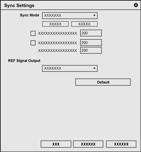
This is a synchronization setting between the monitor output device used for the capture and the Grass Valley hardware, or the output device used for tape output and the Grass Valley hardware.
|
[Sync Mode] |
Select a sync signal from [REF Input Sync] and [Input Sync]. [NO SIGNAL]/[SIGNAL OK] indicates whether a reference signal which can be synchronized with the current output video format is detected. It will switch to internal sync system when the reference signal is not input ([NO SIGNAL]). It can be synchronized to both [Tri-Level] (tri-level sync) and [BB] (Black Burst) signals when [REF Input Sync] is selected and the output format is HD. The box next to the corresponding signal ([Tri-Level] or [BB]) will light in green when either signal is input. It can only synchronized against the [BB] signal when the output format is SD. [Tri-Level HD H-shift] Enter the horizontal-shift adjustment value for the tri-level sync signal during HD format output. [BB HD H-shift] Enter the horizontal-shift adjustment value for the BB signal during HD format output. [SD H-shift] Enter the horizontal-shift adjustment value for the BB signal during SD format output. |
|
[REF Signal Output] |
Selects the format to output the REF signals from [BB NTSC], [BB PAL], [Tri-Level 1080/59.94i], [Tri-Level 1080/50i], [Tri-Level 1080/23.98PsF],and [Tri-Level 1080/24PsF]. For STORM 3G Elite, the [Ref Out SD] indicator on the front of STORM 3G Elite MIP will light up when [BB NTSC] or [BB PAL] is selected, and the [Ref Out HD] indicator on the front of STORM 3G Elite MIP will light up when [Tri-Level 1080/50i], [Tri-Level 1080/23.98PsF], or [Tri-Level 1080/24PsF] is selected. |
|
[Default] |
Restores to the default setting. |
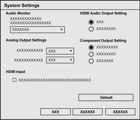
This is the setting for the monitor output device used for capturing.
|
[Audio Monitor]/[Analog Audio Monitoring] |
Selects the audio channel to monitor. |
|
[HDMI Audio Output Setting] |
Sets the output from the HDMI connector. Select whether to output the signals as 8 channels or to output them according to the channel settings specified for the analog 2 channels. |
|
[Analog Output Settings] |
[Setup Level] Sets the setup level (black level) of NTSC from [0IRE] or [7.5IRE]. 0 IRE is used in Japan, and 7.5 IRE is used in North America. [Component Level] Selects the component level from [SMPTE] or [BETACAM]. |
|
[Component Output Setting] |
[Multi Format] HD/SD is switched automatically according to the input format. [SD Only - YPbPr] The downconverted video (component YPbPr) is output. [SD Only - Y/C] The downconverted video (S-Video) is output. |
|
[HDMI Input] |
[Disable FIR filter at RGB/YUV444 to YUV422 conversion.] Check this option to disable the FIR filter when converting to YUV422, which is the color space used for digital TV. |
|
[Default] |
Restores to the default setting. |
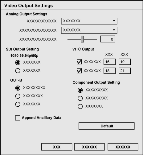
This is a setting for the monitor output device used for the capture or the output device used for tape output.
|
[Analog Output Settings] |
[Setup Level] Sets the setup level (black level) of NTSC from [0IRE] or [7.5IRE]. 0 IRE is used in Japan, and 7.5 IRE is used in North America. [Component Level] Selects the component level from [SMPTE] or [BETACAM]. [Component Gain] Adjusts the output gain of the SD component. |
|
[SDI Output Setting]: [1080 59.94p/50p] |
This is a setting used to output 1080 59.94p or 1080 50p signal from the SDI OUT terminal of STORM 3G Elite. [1x 3G-SDI] It is output as 3G-SDI from the SDI OUT (A) terminal and the SDI OUT (B) terminal. [2x HD-SDI] It is output as HD-SDI x 2 using the SDI OUT (A) terminal and the SDI OUT (B) terminal. |
|
[SDI Output Setting]: [OUT-B] |
This is an output setting for the SDI OUT (B) terminal of STORM 3G Elite. [Multi Format] HD/SD is switched automatically according to the output format. [1080i when 1080p] The video is output in 1080i format when the output format is 1080p. [SD Only] The downconverted video is output. |
|
[VITC Output] |
[Line 1]/[Line 2] Sets the number of lines for VITC output in the input field of adopted video standard (NTSC/PAL). |
|
[Component Output Setting] |
[Multi Format] HD/SD is switched automatically according to the input format. [SD Only - YPbPr] The downconverted video (component YPbPr) is output. [SD Only - Y/C] The downconverted video (S-Video) is output. |
|
[Append Ancillary Data] |
Check this option to output video appended with ancillary data such as closed caption. |
|
[Default] |
Restores to the default setting. |
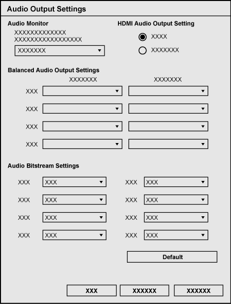
This is a setting for the monitor output device used for the capture or the output device used for tape output.
|
[Audio Monitor] |
Selects the audio channel to monitor. |
|
[HDMI Audio Output Setting] |
Sets the output from the HDMI connector. Select whether to output the signals as 8 channels or to output them according to the channel settings specified for the analog 2 channels. |
|
[Balanced Audio Output Settings] |
[Output Headroom[dB]] Sets the headroom of the reference output level from [20], [18], [16], or [12]. [Output Level[dBm]] Sets the reference output level from [+4], [0], [-3], [-6], or [-20]. |
|
[Audio Bitstream Settings] |
Sets how to handle digital audio signal when outputting SDI embedded audio. The audio bitstream is output if playback data contains audio bitstream, and linear PCM data is output if it does not contain audio bitstream when [Auto] is selected. The linear PCM data is output when [LPCM] is selected. The AC-3 audio bitstream is output when [AC-3] is selected. The Dolby-E audio stream is output when [Dolby-E] is selected. |
|
[Default] |
Restores to the default setting. |
This is a setting for the monitor output device used for the capture or the output device used for tape output.
|
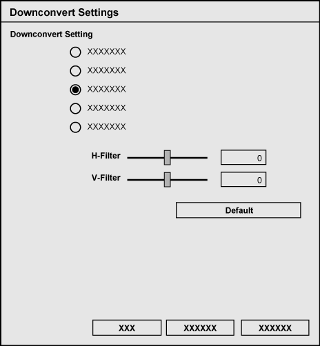
[Downconvert Setting] |
Selects the downconvert format from HD to SD. The default value is [Side Cut]. [Squeeze] Compresses 16:9 video horizontally and outputs as 4:3 video. 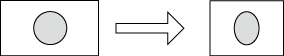 [Letter Box] Masks the upper and bottom part of the 4:3 screen and outputs 16:9 video in the center of the screen. 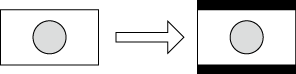 [Side Cut] Cuts the side edges of 16:9 video and outputs as 4:3 video. 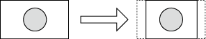 [14:9] Cuts the side edges of 16:9 video and outputs as 14:9 video.  [13:9] Cuts the side edges of 16:9 video and outputs as 13:9 video.  |
|
[H-Filter] |
Emphasizes the horizontal outline and change in contrast of the image. Sets between - 32 and 32. |
|
[V-Filter] |
Emphasizes the vertical outline and change in contrast of the image. Sets between - 32 and 32. |
|
[Default] |
Restores to the default setting. |
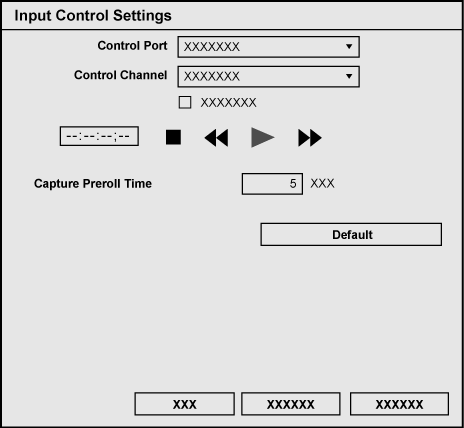
This is the setting for the input device used for capturing.
|
[Control Port] |
Not available. |
|
[Control Channel] |
Selects to use RS-422 remote control or not. For STORM 3G Elite, the [Remote A] or [Remote B] indicator on the front of STORM 3G Elite will light up when [RS422 REMOTE A] or [RS422 REMOTE B] is selected. The control status for the deck connected to the REMOTE terminal can be checked with the playback button, etc. [Use TC Input Terminal] The TC terminal is prioritized to acquire the TC (timecode) information. |
|
[Capture Preroll Time] |
Sets the preliminary operation time (preroll) from the start of capturing. |
|
[Default] |
Restores to the default setting. |
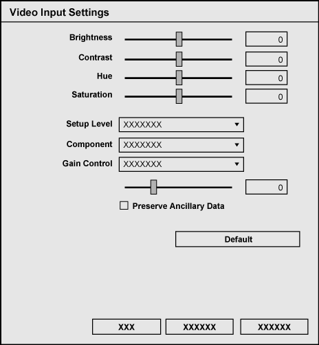
This is the setting for the input signal adjustment used for capturing.
The setting is available only for the component, S-video, or composite input.
|
[Brightness] |
Adjusts the brightness of video. It will become darker when the value is smaller, and brighter when the value is larger. |
|
[Contrast] |
Adjusts the contrast of image. The contrast will be weaker when the value is smaller, and stronger when the value is larger. |
|
[Hue] |
Adjusts the hue of video. Red will be stronger when the value is smaller, and green will be stronger when the value is larger.
|
|
[Saturation] |
Adjusts the deepness of the color. The color becomes lighter when the value is smaller, and deeper when the value is larger. The image will become grayscale when set to 0 (minimum value). |
|
[Setup Level] |
Sets the setup level (black level) for NTSC. |
|
[Component] |
Selects the component level for NTSC. |
|
[Gain Control] |
Sets the video luminance. [Manual] will set the luminance manually. [Automatic] will set the luminance to optimum automatically. |
|
[Preserve Ancillary Data] |
Check this to append ancillary data such as closed caption during capturing. |
|
[Default] |
Restores to the default setting. |
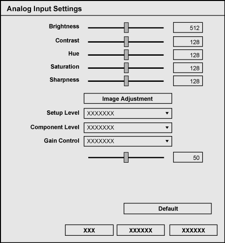
This is the setting for the input signal adjustment used for capturing.
The setting is available only for the component, S-video, or composite input.
|
[Brightness] |
Adjusts the brightness of video. It will become darker when the value is smaller, and brighter when the value is larger. |
|
[Contrast] |
Adjusts the contrast of image. The contrast will be weaker when the value is smaller, and stronger when the value is larger. |
|
[Hue] |
Adjusts the hue of video. Red will be stronger when the value is smaller, and green will be stronger when the value is larger when yellow is used as reference.
|
|
[Saturation] |
Adjusts the deepness of the color. The color becomes lighter when the value is smaller, and deeper when the value is larger. The image will become grayscale when set to 0 (minimum value). |
|
[Sharpness] |
Adjusts the sharpness of the outline in video. The outline is blurred more when the value is smaller, and outline is enhanced when the value is larger. |
|
[Image Adjustment] |
Display the [Image Adjustment Settings] dialog box. |
|
[Setup Level] |
Sets the setup level (black level) for NTSC. |
|
[Component Level] |
Selects the component level for NTSC. |
|
[Gain Control] |
Sets the video luminance. [Manual] will set the luminance manually. [Automatic] will set the luminance to optimum automatically. |
|
[Default] |
Restores to the default setting. |
|
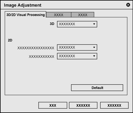
[3D] |
Sets the 3D noise reduction and effect of the 3D visual processing (only for the composite input). |
|
[2D] |
Removes the noise with nonlinear noise reduction filter. It is possible to set separately from the 3D processing. [Luminance NR] Sets the effect of the noise reduction in luminance (Y). [Chroma NR] Configures the effect of the noise reduction in chroma (C). |
|
[Default] |
Restores to the default setting. |
|
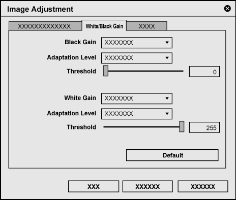
[Black Gain] |
Increases the gain for the low luminance area against the luminance signal. Black is emphasized more by increasing the setting. Items for [Adaptation Level] and [Threshold] will be disabled when set to [None]. |
|
[Adaptation Level] |
Sets the black expansion correction level. Black is emphasized more when the correction level is higher. |
|
[Threshold] |
Sets the level of the luminance (brightness) to emphasize black. It is set to brighter level when the cursor is moved right. |
|
[White Gain] |
Reduces the gain in the high luminance area against the luminance signal. Improves the tone reproduction of a part which is whitened out due to the high luminance. Items for [Adaptation Level] and [Threshold] will be disabled when set to [None]. |
|
[Adaptation Level] |
Sets the white gain limitation correction level. The white gain is corrected less when the limitation level is higher. |
|
[Threshold] |
Sets the level of the luminance (brightness) to correct the white level lower. It is set to darker level when the cursor is moved left. |
|
[Default] |
Restores to the default setting. |
|
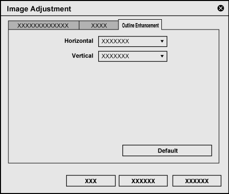
[Horizontal] |
Sets the outline correction in the horizontal direction (the edge of the horizontal line). |
|
[Vertical] |
Sets the outline correction in the vertical direction (the edge of the vertical line). |
|
[Default] |
Restores to the default setting. |
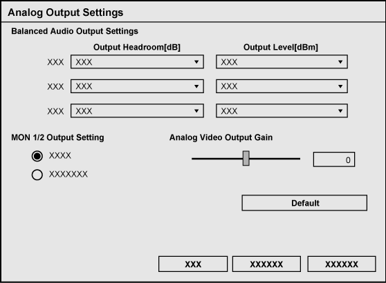
This is the setting for the monitor output device used for capturing.
|
[Balanced Audio Output Settings] |
[Output Headroom[dB]] Sets the headroom of the reference output level from [20], [18], [16], or [12]. [Output Level[dBm]] Sets the reference output level from [+4], [0], [-3], [-6], or [-20]. |
|
[Output Headroom[dB]] |
Sets the headroom from the reference output level from [20], [18], [16], or [12]. |
|
[Output Level[dBm]] |
Sets the reference output level from [+4], [0], [-3], [-6], or [-20]. |
|
[MON 1/2 Output Setting] |
Sets the output from the MON 1 terminal and MON 2 terminal. Selects whether to output from 2ch of the audio monitor set by [Audio Monitor] in [System Settings], or from Ch5/Ch6 of the balanced audio. |
|
[Analog Video Output Gain] |
Sets the output gain for the analog video output terminal. The value can be set between - 64 and 64. |
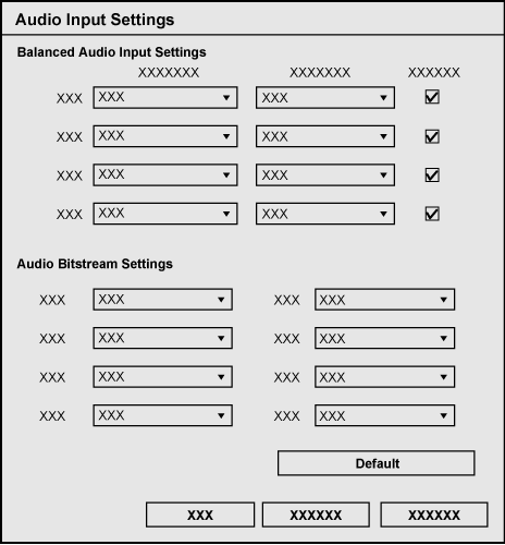
This is a setting for the input device used for the capture or the output device used for tape output.
|
[Balanced Audio Input Settings] |
[Input Headroom[dB]] Sets the headroom from the reference input level from [20], [18], [16], or [12]. [Input Level[dBm]] Sets the reference input level from [+4], [0], [-3], [-6], or [-20]. [600 ohm Termination] Check this option to enable 600 Ω terminator of the balanced audio input terminal. This can be set for each channel individually. |
|
[Audio Bitstream Settings] |
Sets the handling of the digital audio signal for SDI embedded audio input. It will be saved as linear PCM data and handled as normal audio signal during editing when [LPCM] is selected. It will be saved as AC-3 audio bitstream when [AC-3] is selected. It will be saved as Dolby-E audio stream when [Dolby-E] is selected. |
|
[Default] |
Restores to the default setting. |
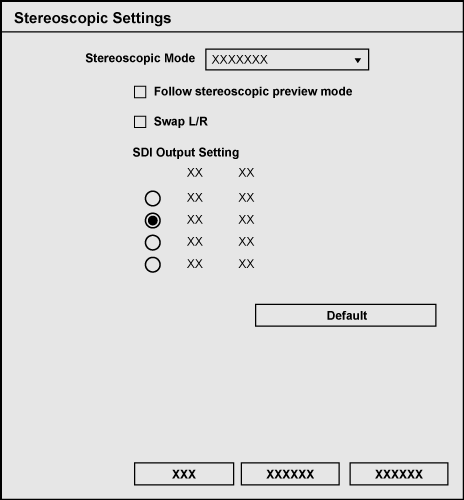
This is a setting for the input device used for the capture or the output device used for tape output.
|
[Stereoscopic Mode] |
Selects the stereoscopic processing format when the video for L side and R side in the project created with the stereoscopic edit mode is output. The video for L side and R side is output as 2 streams when [L/R Dual Stream] is selected. The video for L side only or the R side only is output when [L Only]/[R Only] is selected. The videos of L side and R side are combined and output when [Side by Side]/[Top and Bottom]/[Line Interleave]/[Blend]/[Anaglyph]/[Difference]/[Split Grid] is selected. |
|
[Follow stereoscopic preview mode] |
Outputs in the same format as the preview window display in the stereoscopic edit mode. |
|
[Swap L/R] |
Check this to output with L side and R side inversed. |
|
[SDI Output Setting] |
Set how to output 2 streams from the SDI OUT terminal when [L/R Dual Stream] is selected for STORM 3G Elite. [OUT-A]: [L], [OUT-B]: [R] Outputs the L side video from the SDI OUT (A) terminal, and the R side video from the SDI OUT (B) terminal. [OUT-A]: [3G], [OUT-B]: [3G] Outputs the L+R (3G-SDI) video from the SDI OUT (A) terminal, and the L+R (3G-SDI) video from the SDI OUT (B) terminal. [OUT-A]: [3G], [OUT-B]: [L] Outputs the L+R (3G-SDI) video from the SDI OUT (A) terminal, and the L side video from the SDI OUT (B) terminal. [OUT-A]: [3G], [OUT-B]: [L(SD)] Outputs the L+R (3G-SDI) video from the SDI OUT (A) terminal, and the L side video from the SDI OUT (B) terminal is downconverted to SD and output. |
|
[Default] |
Restores to the default setting. |
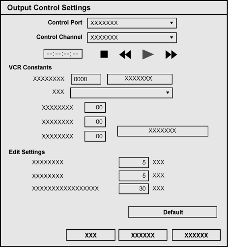
This is the setting for the output device used for output to tape.
|
[Control Port] |
Not available. |
|
[Control Channel] |
Selects the terminal to control the device from the list. For STORM 3G Elite, the [Remote A] or [Remote B] indicator on the front of STORM 3G Elite will light up when [RS422 REMOTE A] or [RS422 REMOTE B] is selected. The control status for the deck connected to the REMOTE terminal can be checked with the playback button, etc. |
|
[VCR Constants] |
[VCR ID(V)] Displays the VCR Constant 1 byte1 and byte2. Displays the deck ID (including model/mode) for SONY decks. [Check for Deck ID] Click it to load VCR ID (deck ID) from the connected VCR. [VCR] Displays the deck name corresponding to the VCR ID. (Only the preset ID and VCR name) Displays all if multiple decks with the same ID are registered. [Edit Delay] Displays VCR Constant 1 Byte 6. Enter manually if the deck is not in the preset. [E-E Delay] Displays VCR Constant 1 Byte 5. Enter manually if the deck is not in the preset. [Start Delay] Displays VCR Constant 2 Byte 2 (Data 10 depending on the deck). Enter manually if the deck is not in the preset. [Load Default Presets] Initializes the edit delay, E-E delay, and start delay with the preset values. |
|
[Edit Settings] |
[Preroll Time] Sets the preliminary operation time (preroll). [Postroll Time] Sets the post operation time (postroll). [FirstEdit Pre-Rec Time] Sets the draft (margin) length at FirstEdit (automatically record the control signal to be the reference point for editing at the top of the tape). |
|
[Default] |
Restores to the default setting. |
The following explains how to register device presets when using a Grass Valley product for input/output.
In the example in this section, the Grass Valley product STORM 3G is attached and used for SDI input/output. The operation procedure is basically the same also when you use other Grass Valley products.
Since detailed settings items differ for each product, see the user manual included with the product.
1) Click [Settings] on the menu bar, and click [System Settings].
|
|
|---|
|
2) Click the [Hardware] tree, and click [Device Preset].
3) Click [New].
[Preset Wizard] will start up.
Alternative
Right-click a blank area in the [Device Preset] list, and click [New].
4) Enter the name of the device preset.
5) Click [Select Icon], select the icon image, and click [OK].
To use any image you like, click [...] and select a file.
6) Click [Next].
7) Click the list in [Interface], and select [STORM 3G].
The name of the attached product is displayed as an interface at the list at [Interface]. Select the interface to use for input.
You can make input settings by clicking [Settings] to the right of [Stream]. For more information, see the user manual included with the product.
8) Click the list in [Video Format], and select the video format of the source to capture.
9) Click the list in [Codec], and select the codec to use for capture.
Depending on the selected codec, click [Settings] to set the codec details.
[Settings - Grass Valley HQ]/[Settings - Grass Valley HQX] Dialog Box
[Settings - XDCAM EX Compatible] / [Settings - XDCAM HD Compatible] Dialog Box
10) If necessary, set other items and click [Next].
11) Click the list in [Interface], and select [STORM 3G].
The name of the attached product is displayed as an interface at the list at [Interface]. Select an interface to use for output.
To disable use of a hardware product for output, select [Not Select] and proceed to step 13) .
You can make output settings by clicking [Settings] to the right of [Stream]. For more information, see the user manual included with the product.
12) Click the list in [Video Format], and select the video format of the source to capture.
13) If necessary, set other items and click [Next].
14) Confirm the details, and click [Done].
The icon of the newly created preset is displayed in the device preset list.