Removing and replacing FRUs
Field Replaceable Units (FRUs) are modular hardware components that can be serviced without disturbing other components in the system. The following topics discuss working with the Turbo iDDR FRUs.
- "Top cover removal"
- "Front bezel removal"
- "Rotary encoder removal"
- "Front panel board removal"
- "Removable media drive removal"
- "SATA drive removal"
- "Front connector board removal"
- "Fan module removal"
- "Codec board removal"
- "Power supply removal"
- "Riser board removal"
- "IEEE 1394 adapter removal"
- "RS-422 adapter removal"
- "XLR board removal"
- "CPU motherboard removal"
The pictures in these topics show how to disassemble. Unless otherwise documented, re-assembly is the reverse.
Unless otherwise indicated, you need only a Torx tool with T15 magnetic tip to remove and replace parts in the Turbo iDDR.
You can also replace the entire Turbo iDDR as a FRU, as explained in "Replacing an iDDR".
NOTE: Only Grass Valley components are supported. Do not attempt to use components procured from a different source.
NOTE: Do not discard any hardware unless specifically instructed to do so.
WARNING: To avoid serious injury from high currents, ensure that the power cord is disconnected prior to removing or replacing any parts.
CAUTION: This system contains board-level components that must be protected from static discharge and physical shock. Wear a wrist strap grounded through one of the system's ESD Ground jacks when handling system components.
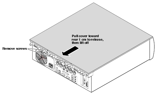
Top cover removal
To access the internal hardware, first remove the top cover as follows:
CAUTION: To avoid possible damage to circuit boards and other sensitive parts, turn off the iDDR and disconnect AC power before opening the top cover or removing any internal parts.
For an overview orientation of internal FRUs, refer to "FRU locations".
Front bezel removal
To remove the bezel, first remove the top cover, then proceed as illustrated.
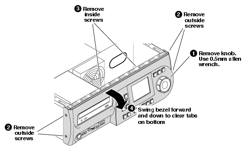
NOTE: When installing the bezel, make sure the bottom tabs are engaged and the button openings are aligned before tightening screws.
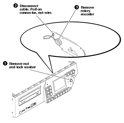
Rotary encoder removal
To remove the rotary encoder, first remove the top cover and bezel, then proceed as illustrated.
Front panel board removal
To remove the front panel board, first remove the top cover and the front bezel, then proceed as illustrated. It is not necessary to remove the rotary encoder.
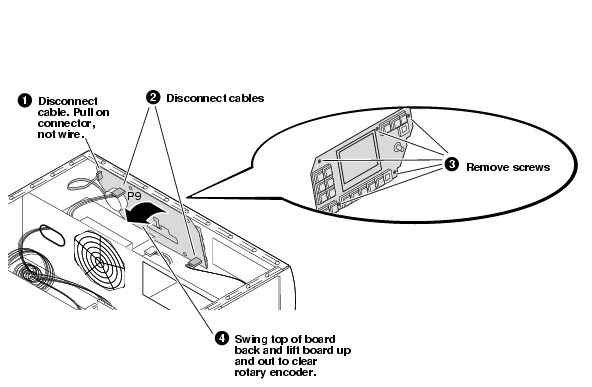
Shown with DVD drive removed for clarity.
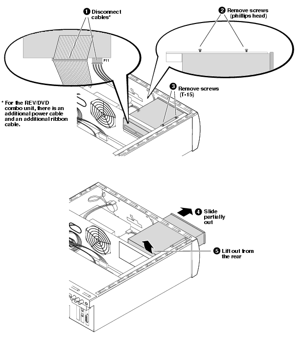
Removable media drive removal
To remove the DVD drive or the REV/DVD drive combo, first remove the top cover then proceed as illustrated.
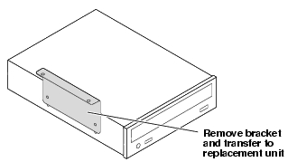
For the DVD drive, you must exchange the bracket with the replacement unit, as in the following illustration.
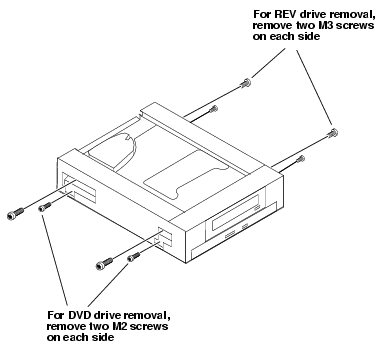
For the REV\DVD drive combo, you must remove the faulty drive from the bracket. When you do so, retain the bracket, as you must use it again with the replacement unit.
Use the following diagram to disassemble the REV\DVD drive combo:
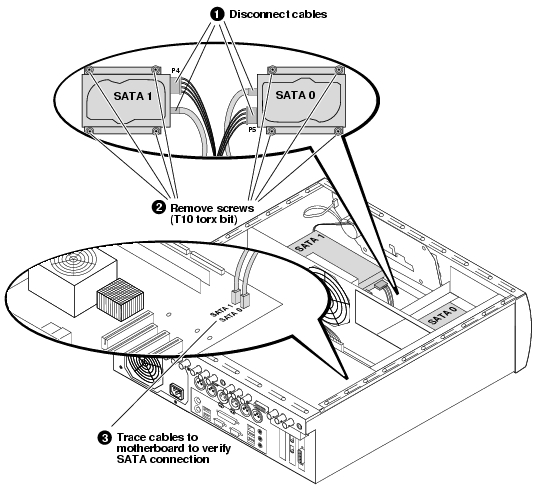
SATA drive removal
To remove SATA 1 first remove the top cover. To remove SATA 0, additionally remove the DVD drive, then proceed as illustrated.
Before installing the replacement SATA drive in the chassis, remove the brackets on the faulty SATA drive and install them on the replacement SATA drive.
After replacing either one SATA drive or both SATA drives, you must restore the system. Refer to "Restoring the default system".
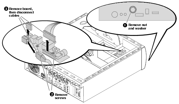
Front connector board removal
To remove the front connector board, first remove the top cover, the front bezel, and the DVD drive, then proceed as illustrated.
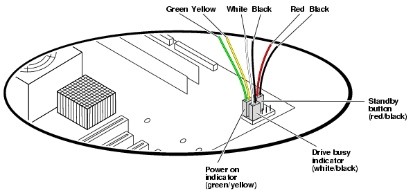
If you disconnect the front interconnect board wiring from the motherboard, refer to the following illustration to re-connect the color-coded wires in the correct orientation:
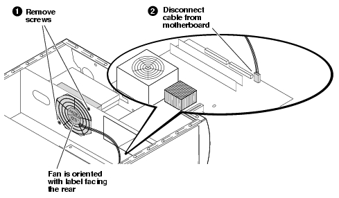
Fan module removal
To remove the fan module, first remove the top cover, then proceed as illustrated.
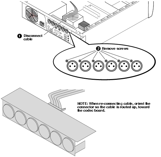
Codec board removal
To remove the codec board, first remove the top cover, then proceed as illustrated.
After the replacement codec board is installed, use the system installer process as explained in "Restoring the default system" and select System Update/Repair to ensure the codec board and the system software versions are compatible.
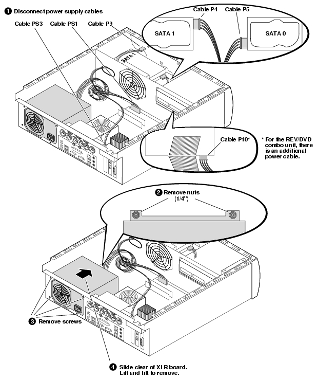
Power supply removal
To remove the power supply, first remove the top cover and the codec board, then proceed as illustrated.
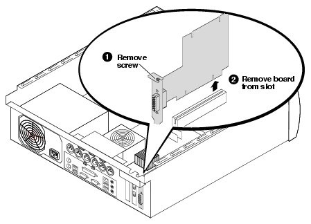
Riser board removal
To remove the riser board, first remove the top cover and the codec board, then proceed as illustrated.
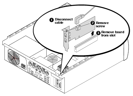
IEEE 1394 adapter removal
To remove the IEEE 1394A adapter, first remove the top cover and the codec board, then proceed as illustrated.
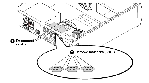
RS-422 adapter removal
To remove the RS-422 adapter, first remove the top cover and the codec board, then proceed as illustrated.
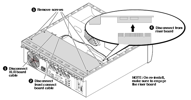
XLR board removal
To remove the XLR board, first remove the top cover, the codec board, and the RS-422 adapter, then proceed as illustrated.
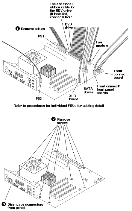
CPU motherboard removal
To remove the motherboard, first remove all boards in the rear of the chassis, then proceed as illustrated.
|
|
| Copyright Thomson Broadcast and Media Solutions, Inc. |
| http://www.thomsongrassvalley.com |