Product Description
Topics in this section include the following:
- "Product documentation"
- "Overview description"
- "System description"
- "Media control and processing"
- "Turbo iDDR orientation"
- "FRU functional descriptions"
- "Status indicators"
Product documentation
This manual is part of a full set of support documentation for the Turbo iDDR.
On-line Help
You can access the on-line help through the AppCenter Workstation user interface which is available when you operate the Turbo iDDR using a VGA monitor, mouse, and keyboard.
To access online help in AppCenter:
Thomson Grass Valley Web site
This public Web site contains all the latest manuals and documentation, and additional support information. Use the following URL.
http://www.thomsongrassvalley.com.
See also "Obtaining Technical Assistance".
Overview description
The Turbo iDDR is a multi-channel video disk recorder with one record channel and two playback channels. Record and playback can occur simultaneously. Media is stored on internal disk drives. Storage capacity depends on the video compression settings selected.
The iDDR includes a built in disk recorder application that handles essential tasks — record, edit, play, and create/play event lists. The front panel includes an LCD display with touch screen and transport controls to allow easy operation with minimal external connections.
Refer to the Turbo User Manual for other high-level descriptions of features, controls, and applications.
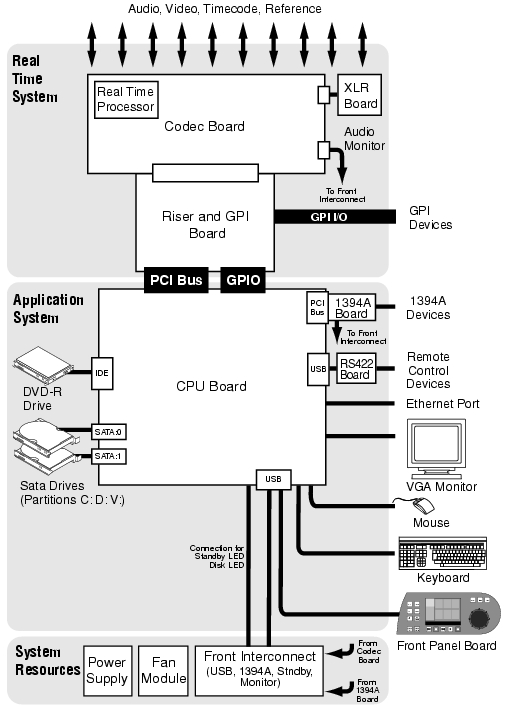
System description
The Turbo iDDR is a standard PCI bus-based Windows computer with extensive enhancements to provide the video disk recorder functionality. This section explains the major architectural blocks.
Application System
The Application system architecture is similar to that of standard PC-type computers. It uses an ATX form factor motherboard. The iDDR has a standard PCI board as follows:
In addition, the following board has an internal USB connection:
The Application system uses a Windows XP embedded operating system upon which all Turbo iDDR applications run for configuration and control of the iDDR. The front panel application runs on Windows CE operating system.
The SATA drives are adapted and configured by Grass Valley for use in the iDDR. There are three partitions, mapped to the Windows operating system using the C:, D:, and V: drive letters. The C: drive contains the operating system and application software. The D: drive contains the media database and configuration files. The V: drive is striped across both SATA drives and contains the media.
Real Time System
The Real Time system uses Grass Valley boards to provide the core video disk recorder functionality. Primary components are as follows:
- Codec Board — This board hosts the circuits responsible for encoding/decoding video, processing audio, processing timecode, and provides the majority of the iDDR’s media-related input and output connectors. It also hosts the Real Time Processor (RTP), which is the dedicated processor for the Real Time system.
- XLR Board — This board provides XLR audio connectors. It is primarily an extension of the codec board to allow the space and orientation required for XLR connections.
- Riser Board — This board connects to the PCI slot below and the Codec board above. It also provides one GPI connector.
The Real Time system uses a dedicated operating system. This operating system runs on the Real Time Processor and manages all the hardware involved in controlling the flow of video, audio, timecode, genlock, and GPI in and out of the iDDR.
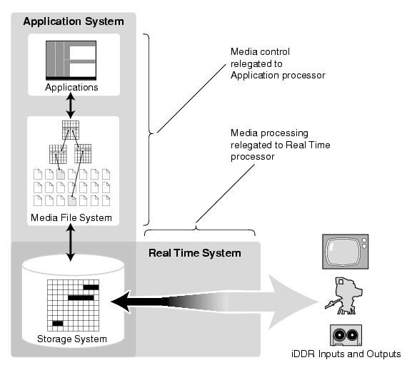
Media control and processing
The following section explains how the Application system and the Real Time system work together to provide iDDR functionality.
The high processing requirements of digital video can overwhelm the processor on a standard desktop PC, resulting in wait-times that destroy the video’s essential real-time aspect. The iDDR avoids this problem by providing dedicated systems that isolate processing needs. The components that work together to provide this functionality are as follows:
The Application system is, at its core, a conventional desktop PC-type system. In the iDDR it is dedicated to control, configuration, and networking functions that do not require real-time accuracy. The Application system has the following components:
- Application software provides the user interface for operating the iDDR. The software runs as Windows programs. Application servers use DCOM, a standard Microsoft technology, which allows both local and remote operation.
- The Media File System manages clips. It includes a database that associates the clip with its video, audio, and timecode files. It uses the Windows file system to control access to the raw data that makes up each file. Any reading and writing of clips, be it through play and record operations or through file transfers and media streaming, is managed by the database. The database and file system run as Windows programs.
The Storage System includes the V: partition on the SATA drives, controllers, drivers, and adapters necessary for access and movement of the data. The primary data flow is within the overall control of the Real Time System.
The Real Time System manages the media flow between the Storage System and the iDDR inputs and outputs. The Real Time system has a dedicated processor and time-sensitive mechanisms to serve media processing needs while maintaining real-time accuracy.
When you control iDDR play and record operations from within the Application System you trigger a chain of events that eventually crosses over into the Real Time System and results in media access. The following sequence is an example of this type of chain of events:
- A user operates the Player application to play a particular clip. The Player application communicates with the Media File System to initiate play access to the clip.
- The database identifies the files that make up the clip and the file system instructs the Storage System to open access to the files.
- The Storage System finds the raw data and opens the appropriate read access. At this point both the Application system and the Real Time system are involved. Windows controls the media drives and controllers, so the Real Time system makes file requests to Windows and it causes the data to be transferred to buffers on the Real Time Processor. The data is then available to the Real Time System so that it can be processed at exactly the right time.
- The Real Time System processes the media, decompresses it, adjusts its timing, and moves it as required to play the clip as specified by the user.
iDDR services
The following Windows services run during operation to allow specific iDDR functionality:
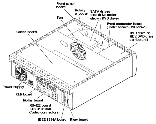
Turbo iDDR orientation
This section describes the major hardware pieces that make up the iDDR.
FRU locations
To view the Turbo iDDR’s Field Replaceable Units (FRUs), first remove the top cover, as explained in "Top cover removal". The FRUs are located as follows:
FRU functional descriptions
The Field Replaceable Units (FRUs) described in this section are as follows:
- "Base chassis"
- "Front panel"
- "Rotary encoder"
- "Front connector board"
- "SATA drives"
- "Removable media drives"
- "Fan module"
- "Power supply"
- "Codec board"
- "Riser board"
- "XLR board"
- "RS-422 adapter"
- "IEEE 1394 adapter"
- "CPU motherboard"
For procedures, refer to "Removing and replacing FRUs".
Base chassis
For some serious system faults or for mechanical damage the entire iDDR, as described earlier in this chapter, can be replaced as a base chassis FRU. Refer to "Replacing an iDDR".
Front panel
The front panel provides a control panel user interface for the Turbo iDDR. The front panel includes the following components:
- The display is a 320 by 240 TFT display.
- Buttons are provided for transport controls, edit controls, display controls, and jog/shuttle controls and a variable speed play control.
- The multi-function knob provides control for jog, shuttle, variable speed play, scrolling through menu items on the display, and selecting menu items on the display. The complete multi-function knob mechanism can be replaced as the rotary encoder FRU.
- Buttons and the knob have integrated LEDs that light up when the control is activated.
Refer to "Front panel board removal" for procedures.
Refer to the Turbo User Manual for instructions on using the front panel.
Rotary encoder
This is the complete mechanism which includes the front panel multi-function knob and the canister in which it is housed. In case it is damaged or otherwise inoperable, it can be replaced separately from the front panel.
Refer to "Rotary encoder removal" for procedures.
Front connector board
The front connector board provides a standby button, a power on indicator, and a drive busy indicator. A headphone jack and volume control is provided for audio monitoring. Connectors include one IEEE 1394 port and one USB 2.0 port.
Refer to "Front connector board removal" for procedures.
SATA drives
There are two SATA drives in the iDDR. They are located in the front of the unit. One is behind the front panel and the other is under the DVD drive. Storage for all systems, including applications, file systems, and media storage, is integrated on the SATA drives. There are no independent drives exclusively for media storage.
Media data has its own partition on the SATA drives. The media is written or “striped” across the drives in a continuous fashion, which makes the two drives a “stripe group”. The media stripe group appears as the V: drive to the Windows operating system. Because of this stripe group relationship, if one SATA drives is removed or is faulty, all data is lost on the entire stripe group.
Other partitions on the SATA drives include the C: drive for application and operating system files, and the D: drive for the media database and configuration information.
Refer to "SATA drive removal" for procedures.
Removable media drives
The iDDR uses standard removable media drives similar to those found in desktop PCs. The drives are installed in the drive bay, which is accessed from the front of the iDDR. These drives use standard Windows drivers for easy plug-and-play installation. Turbo iDDR options for removable media drives include the following:
Refer to "Removable media drive removal" for procedures.
Fan module
The fan module provides cooling for the iDDR chassis. Air intake is from the front of the iDDR and outflow is through the rear. The fan module is installed on the center support partition in the iDDR chassis.
Refer to "Fan module removal" for procedures.
Power supply
The iDDR power supply has a fan with automatic speed control and status LEDs that indicate the current state and health of the power supply. Refer to "Power supply problems" for LED descriptions. The power supply has protection for over voltage, over current, over temperature, and short circuits.
Refer to "Power supply removal" for procedures.
Codec board
The codec board is oriented horizontally across the rear of the iDDR chassis. It provides the majority of the iDDR’s media-related input and output connectors on the rear panel. This board hosts the circuits responsible for encoding/decoding video and processing audio and timecode. It also hosts the Real Time Processor. It is connected to the motherboard via the riser board.
Refer to "Codec board removal" for procedures.
Riser board
This board connects to the PCI slot below and the codec board above. It also provides one GPI connector.
Refer to "Riser board removal" for procedures.
XLR board
The XLR Board provides XLR audio connectors at the iDDR rear panel. It is primarily an extension of the codec board to allow the space and orientation required for XLR connections. It is connected via cable to the codec board.
Refer to "XLR board removal" for procedures.
RS-422 adapter
The RS-422 adapter is oriented horizontally in the center of the iDDR rear panel area. It is located between the codec board and the XLR board. It provides three RS-422 ports for connecting equipment for remote control of the iDDR. It is connected via an internal USB cable to the motherboard.
Refer to "RS-422 adapter removal" for procedures.
IEEE 1394 adapter
The IEEE 1394A (FireWire) adapter provides two ports. These ports can be used for importing and recording media from a digital recording device that uses DV or HDV format. The IEEE 1394A adapter is connected to the motherboard via one of the standard PCI slots on the motherboard. A cable connects the IEEE 1394A adapter to the front connector board.
Refer to "IEEE 1394 adapter removal" for procedures.
CPU motherboard
The iDDR uses a ATX motherboard with an Intel P4 processor. It is located in the bottom rear of the iDDR chassis.
Refer to "CPU motherboard removal" for procedures.
Status indicators
The following sections describe the visual and audible indicators that communicate the current operating status and system health of the Turbo iDDR.
Front panel indicators
Power-On Indicator
This LED indicates status as follows:
Off: The standby switch is set to Off and the Turbo is not operational.
WARNING: The power standby switch does not turn off power to the system. The system must be disconnected from the power source.
Steady on: The standby switch is set to On and the Turbo is operational.
Blinking: Turbo needs service.
Drive busy indicator
When this LED flashes, it indicates that data is being written or read to disk.
System beep codes
The Turbo iDDR BIOS emits one or more audible beeps during start up as part of the Power On Self Test (POST), as described in the following sections:
Normal beep code
If POST completes normally, the BIOS issues one short beep before passing control to the operating system.
Error beep code
When an error occurs during POST, the BIOS issues a beep code of two or more beeps. Any beep code other than the normal beep code (one beep) indicates a problem with the motherboard.
NIC indicator codes
The RJ-45 LAN connector includes integrated status LEDs. The LEDs can be observed from the rear panel of the Turbo iDDR. The LEDs are oriented as follows:
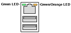
The meaning of the LED states are described in the following table:
If the NIC adapter is faulty, you must replace the motherboard.
BIOS messages
By pressing the Delete key on the keyboard during Turbo start up, you can view BIOS settings and messages. These messages can report problems. Refer to "System Messages".
|
|
| Copyright Thomson Broadcast and Media Solutions, Inc. |
| http://www.thomsongrassvalley.com |